Project
Home
Story
Project
Video
Project
This project should be for a inthusiast and not for a beginner. Sorry to say this but it is more complex then I tought first as I think in 2018 on this motorized tuneabel antenna. You need a lot of tools to build it. It is nothing for a starter or for people they hit the nerves away if something went wrong. If a item (part of this DIY-kit) is not so exact made so you must change this item into a working part.
ATTENTION: it is nothing for children! there are small items/parts that can swallow and so on it is dangerous for small children!
The very long development time occured from the issue of my healthy problem and it was/is a rehab work and I only have had time only a view hours a day and nothing more - so sorry not all the days I've been working on it.
In the 'manual version X' is the step by step howto build this DIY-kit (Do it yourself - kit) and how yo can operate them. Well this is a 1/4 Lambda coil and you can adjust it by alittle motor.
WARNING:
The shield of the coax cable is everytime on ground (GND is zero voltage). The motor is controlled be 3 different voltages. The control and supply power is everytime in the middle of the coax (on the hot wire).
At +9 Volt(stopp) a current from about 30mA is running into the motor controller,
with +8 Volt [~250mA] the motor move down (the coil is shorter and the frequency goes up),
with +10.5 Volt [~250mA] the motor move up (the coil is going longer and the frequency is going down to longer wavelength). The ground is the earth or a very big size of metal sheet like a metal roof. Also you can make a spider wire network around the ground to manage the SWR. A 1/4 Lambda short coil antenna is very critical in haveing a wrong SWR. This DIY-kit not offers a signal like a big antenna that must be understand that is only a experiment with a small one. You have no warranty of working with this antenna, a small signal can transmitt and also signals can received but I said there is no warranty that this antenna is working - It can be.
You need also a external coil to insert the voltage into the hot wire in your coaxial cable this is not include in this DIY-kit. You need a SWR-meter for the measurement of the standing wave and forward/reverse measurement.
In this DIY-kit are more then 100pcs items include so this is to be need to finish this DIY-kit.
DIY-kit is not a fully working and function device!
This DIY-kit is not a mass product and it is made by hand, packed by hand, sort by hand and so on that mean that this DIY-kit is only available in very small volume. There are also CNC-Laser that cut the items/parts out and this must handel by hand and also CNC-Roboter they made the metall-parts for this DIY-kit. I can not answer all the question because I'm allown and can only do some things in a day only for 1-2hours. Please understand this that I can't not answer every email and question. Maybe there is one out in this world that can make a forum board or it will be descusse in a forum board. I don't have the time in the rest of my live.
A Electronic pcb must be made under a obscure situation because I can't calculate them and there I made a wrong design for more then 3 times. On the first pcb the transistors are less strong and they have had 500mA but this was to low because the motor starting phase has more power and the transistor are died. Then I went to a new with better stronger 2A transitors and I used a existing library (I never do this in my live but at this moment I don't think) and Transistors with a pin connection are not exist with ECB (emitter collector base). And I won the next pcb to pay... but now 2A transistors are build in with BCE and it worked. A lot of things went wrong but I think near every item are made 3 times new. :-) Metal item are also made for this antenna and Herry is doing this thing well with CNC-metal laser and CNC-metal production machines. The other acrylic parts are made at my home (there is the CO2 laser in my kitchen for cutting). If you would like to start making some mechanical things you must have a laser this is the ultimate tool for homeworking. No joke!
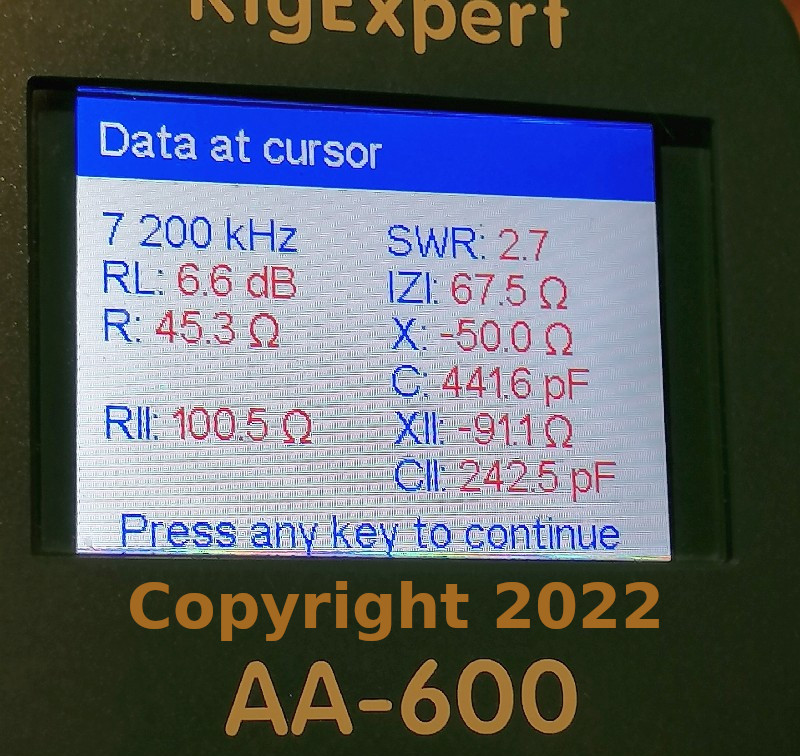
A measurement around 7200kHz on this green field of grass is near impossible - my HAM friend and I we don't trust them. This is a measurement and it is real but 40m Band on such as small antenna it can't work good this is the true. In higher bands are the SWR much better but we think also the connections will be better but this is for experimental porpose the coil have 15meter of wire on it. I would like to do the 60m band too but this is real impossible it is so the name only a experiment. It's fun.
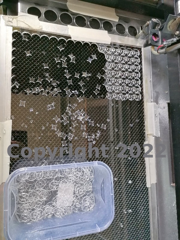
CNC-Laser cutting the items out of acrylic glass
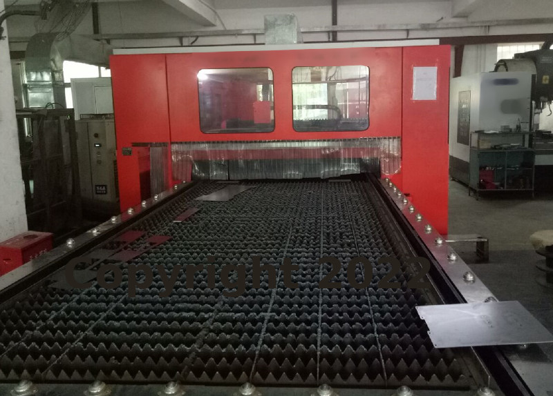
Herry made the CNC-metal items
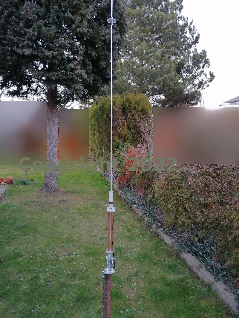
Motorantenna DIY-kit on a good ground
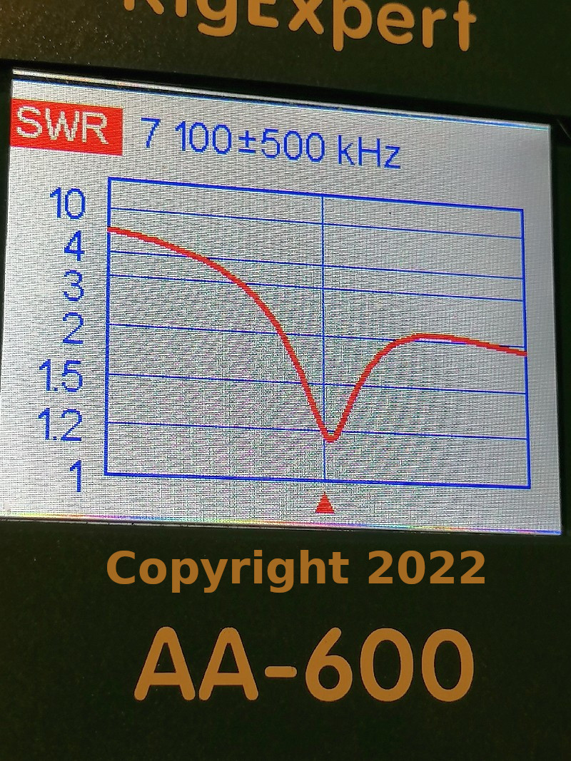
Measurement at around 7100kHz -
Measurement at around 7100kHz - 40m Band
Measurements are correct - but it is a physical need that a long wave need a long antenna. Such a short one can work but it must not. In my experiment are only the idea exist I have no space in my area where I live and so the idea is born to make a very short compact coil with a motor. It should be a remote antenna via voltage controlled. That was the idea of this experiment. Here in my living area it is not allow to build a short-wave antenna in the roof. The property managment will know how much are the static values and you need to order a structural engineer first. Then you need a presentaion of a plan for the installation this is a secound person that is involve in this project and last but not least you need a lightning arrester. All must be installed from professional and will be approved by the property managment.
So what do you think what it will cost?
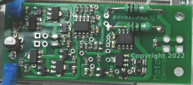
Motor-controller PCB
The motor-controller made the forward/reverse switching. The rectangel holes (right side) are the +Plus pol, the round are the GND (Ground or zero Volt). +9V(30mA) = stopp, +8V(~250mA) = down and +10.5V(~250mA) = up. To the right side are four holes, two of them are rectangular-holes this is the +plus Input and out to the Coil over the RG178 Coax cable. The round-holes are the GND(Ground - zero Volt) - do not change the polarity! +Plus is ever Plus and GND is ever -Ground. The direction of the motor is change by the voltage what you send in this motor-controller.
On the left side are 2 solder points and this is are the motor connection. If the motor go at +8V in the direction up so the polarity is inverse (wrong) swap the wire connection.
On the left side are 4 vias the rectagular-via is connected to the round-via (each of them are one the positive line), if you would like to build in the end-switch so here you can interrupt the pcb-wire and build in a end-switch. This end-switch should be NC (Normal close). In the end of the coil should be open the switch and stop the motor. The positive way to the motor is interrupted.
Tools that you need: solder, soldering-iron, kniff, cutter, side cutter, wire 1.5mm, jaw spanner, cross screwdriver, Glue (to adhere the Transport roth item with the coil), Hot Airgun (to shrink the hose on the coax cable), flat pliers (press the contact on the coax cable), other tools, and a lot of patience for building this DIY-kit.
Howto build: All the steps howto build are described in the
'59antennas_motor_antenna_v1.pdf'
you can download it on the first site of this home page.
How to build a motor-remote?
You need to build a motor-remote for sending up the +9V(30mA)stopp, +8V down and +10,5V up to controll the motor. It is a simple electronic that we must built. We need a 10µH coil (let's do the math => Xl is the coil resistance R(Ohm), Xl = 2PI()*f*L (PI() is 3,1415..., f is frequency, L is impedance).
Example 7100kHz: Xl = 2*PI()* 7100kHz * 10µH = 446 Ohm
Example 14150kHz: Xl = 2*PI()* 14150kHz * 10µH = 889 Ohm
Example 28500kHz: Xl = 2*PI()* 28500kHz * 10µH = 1790 Ohm
to insert the voltage for the motor-controller over the coax-cable (RG213 or better). On the examples we can see that a higher frequency brings a higher Xl impedance on the inserter for the volatge. Also we need 3 sources of voltage. Input +12V and output +9V, +8V and +10.5V via a power regulator.
Special Thanks to all my helpers -
2025 Copyright all rights reserved this page is only for Hobbiest and ethusiast in HAM Radio operation. It include a Do it Yourself Building plan for it's Kit. For the topic of this page responsible is Volker Hois he wrote this page and cutting the Videos Copyright 2018 - 2025 Volker Hois all rights reserved this project ist for my rehab from my organic disease. I can't help you in any case I'm sorry please understand this project take over 7years and I finished it with some step by step from hour to hour doing and I can't work anymore! This is no company and no commercial interest page. If you've any questions plese write a email under the 'Home' is a button 'email us'. But I need time to answer!